


HID Aero X200
Input Monitor
Interface Module
HID Aero X200 — What It Is and How It Works
The dedicated input expansion module for the HID Aero system — monitor up to 16 supervised alarm zones per module, with custom rules logic powered by the X1100
The HID Aero X200 is an Input Monitor Interface IO Module from HID Global, designed to massively expand the input monitoring capacity of an HID Aero X1100 intelligent controller. Unlike the X100 (which adds doors, readers, and relay outputs), the X200 specialises in input monitoring — providing 16 general-purpose supervised or unsupervised inputs, plus 3 dedicated inputs for Tamper, AC Fail, and Battery Fail monitoring, giving 19 total inputs per module.
This makes the X200 ideal for deployments where large numbers of alarm contacts, door position switches, zone sensors, PIR detectors, or other binary input devices need to be monitored centrally — such as perimeter alarm systems, secure storage areas, server rooms, or any application requiring comprehensive zone input monitoring alongside or independent of door access control.
The X200 also includes 2 Form-C relay outputs with dry contacts (rated 2A @ 30V DC) for auxiliary output control — triggering alarm sirens, notification lights, or other output devices based on input state changes.
Critically, the X200 integrates with the custom rules engine on the HID Aero X1100 controller, allowing security integrators to create sophisticated conditional logic based on input states. All communication between the X200 and X1100 is AES-256 encrypted, and crypto chip protection guards stored keys from physical attack.
- Direct replacement for HID VertX V200 — same form factor, compatible wiring
- Each X1100 RS-485 port supports up to 32 X200 modules
- Each X200 contributes 16 general-purpose inputs to the system-wide total of 615 inputs
- All supervised inputs support custom A-to-D conversion thresholds via host software
- Existing VertX V200 RS-485 wiring is fully compatible with the Aero X200
// Quick Reference — HID Aero X200
HID Aero X200 — All 19 Inputs Explained
Understanding the 16 general-purpose inputs and 3 dedicated inputs that give the X200 its comprehensive monitoring capability
16 General-Purpose Inputs
// SUPERVISED OR UNSUPERVISED
- Alarm contacts (NC or NO devices)
- Door position / door status monitoring
- PIR (Passive Infrared) motion detectors
- Window / glass break sensors
- Zone perimeter alarm inputs
- Secure storage area monitoring
- Server room environmental sensors
- General-purpose binary input signals
- Each input configurable as supervised (EOL resistors) or unsupervised
- All supervised inputs support 4-state ADC: open, closed, short, tamper
- Custom EOL thresholds configurable via host software
3 Dedicated Inputs
// TAMPER · AC FAIL · BATT FAIL
- TAMPER — Cabinet/enclosure tamper detection. Triggers alert if the X200 housing is opened or physically interfered with
- AC FAIL — Mains power loss monitoring. Detects when the AC supply feeding the X200 power supply fails
- BATTERY FAIL — Backup battery fault detection. Signals when the UPS backup battery is low, discharged, or faulty
Why Dedicated Inputs Matter
The 3 dedicated inputs (Tamper, AC Fail, Battery Fail) are wired to the X200's physical security and power status — they are separate from the 16 general-purpose inputs and cannot be re-assigned. This ensures power and physical security monitoring is always active regardless of how the general-purpose inputs are configured.
X200 + X1100 Custom Rules Engine
How the HID Aero X200 works with the X1100 custom rules engine to create sophisticated, real-time security automation based on input states
Custom Rules Engine — Logic Flow
The X1100 rules engine monitors X200 input states and triggers configured actions automatically — no operator intervention required
IF — X200 Input Condition
Monitor one or multiple X200 input states (single input, combination, time-based, or correlation)
THEN — X1100 Rules Engine
Evaluates the condition logic defined in the access control software configuration
THEN — Trigger Action
Trigger relay output, send alert, adjust threat level, lock/unlock door, or log security event
Practical Custom Rules Examples
With X200 inputs and the X1100 rules engine, integrators can configure logic such as: IF server room door contact opens AND motion sensor input is not active THEN trigger alarm relay and send alert notification. Or: IF three zone inputs report alarm state simultaneously THEN activate lockdown threat level. Or: IF cabinet tamper input triggers THEN immediately disable all card reader access on the affected floor. This level of conditional security automation is the X200's standout differentiator over basic input expansion modules.
Key Benefits of the HID Aero X200 Module
Why the HID Aero X200 is the definitive input expansion solution for comprehensive zone monitoring in HID Aero access control systems
16 General-Purpose Inputs Per Module
Each X200 adds 16 fully configurable supervised or unsupervised inputs — for alarm contacts, zone sensors, door positions, environmental detectors, or any binary input signal.
- 16 inputs per module × 32 modules per X1100 port
- Up to 615 total inputs in a maximum X1100 system
- Each input independently configurable as supervised or unsupervised
- All supervised inputs support 4-state analogue-to-digital conversion
AES-256 Encrypted Module Communication
All communication between the X200 and the X1100 controller is AES-256 encrypted — ensuring no alarm input data can be intercepted or spoofed on the RS-485 module bus.
- AES-256 encryption on RS-485 bus — X200 to X1100
- Crypto chip protection for stored keys and passwords
- Security upgrade over legacy VertX V200 (no encryption)
- End-to-end security from sensor to host software
Custom Rules Engine Integration
Use the X200 with the X1100's custom rules engine to create elaborate conditional logic based on input states — enabling sophisticated alarm correlation and automated security responses.
- Define complex IF/THEN rules based on X200 input conditions
- Combine multiple input states in a single rule condition
- Trigger relay outputs, threat levels, or access changes automatically
- Rules process locally on X1100 — no host dependency for execution
Direct VertX V200 Replacement
The X200 fits in the same physical footprint as the HID VertX V200, uses the same RS-485 wiring, and represents a security and capability upgrade from the legacy module.
- Same form factor as VertX V200 — fits in same enclosure/panel
- Existing VertX V200 RS-485 wiring fully reusable
- No new cabling required for V200 → X200 upgrade projects
- Adds AES-256, crypto chip, and rules engine — not available in V200
3 Dedicated Monitoring Inputs
Tamper, AC Fail, and Battery Fail dedicated inputs provide constant physical and power security monitoring for the X200 module itself — independent of the 16 general-purpose inputs.
- TAMPER — alerts on enclosure interference
- AC FAIL — monitors mains power supply failure
- BATT FAIL — detects backup battery fault or depletion
- Always active — cannot be repurposed or disabled
2 Form-C Relay Outputs
Two Form-C (changeover) relay outputs with dry contacts — rated 2A @ 30V DC — allow the X200 to trigger alarm devices, notification outputs, or auxiliary equipment in response to input events.
- Form-C contacts: NO (Normally Open), NC (Normally Closed), Common
- Rated 2A @ 30V DC resistive — suitable for most alarm devices
- Non-latching — relay returns to rest state when de-energised
- Can be activated by rules engine or host software commands
HID Aero X200 — Full Technical Specifications
Complete specification reference for the HID Aero X200 Input Monitor Interface Module
Power & Supply
| Input Voltage | 12 to 24 V DC ±10% |
| Power Cable | Minimum 18 AWG wire — use 2-conductor shielded, 18–16 AWG, max 500 ft (150 m) |
| Power Source Requirement | Must be powered from a UL294 Certified limited power source output |
| Ground Connection | Connect to earth ground at ONE location in the system only — multiple earth ground connections may cause interference |
Inputs
| General-Purpose Inputs | 16 (supervised or unsupervised) |
| Dedicated Inputs | 3 — Tamper, AC Fail, Battery Fail |
| Total Inputs per Module | 19 = 16 GP + 3 Dedicated |
| Supervision Mode — Unsupervised | Normally open (NO) or normally closed (NC) contact directly wired — no EOL resistors required |
| Supervision Mode — Supervised | Requires two 1kΩ, 1% end-of-line resistors placed close to the sensor device |
| Standard EOL Resistors | 1kΩ / 1kΩ, 1%, 1/4 watt |
| Custom EOL Thresholds | Configurable via host access control software Configurable |
| ADC Supervision States | 4-state analogue-to-digital conversion: open, closed, short, tamper |
| Alarm Input Cable | One twisted pair, typically 22 AWG — max 500 ft (150 m) for input circuits |
| Custom Rules Processing | All 16 general-purpose inputs accessible to X1100 custom rules engine Feature |
Relay Outputs
| Number of Relays | 2 (Form-C) |
| Relay Contact Type | Form-C — Common (C), Normally Open (NO), Normally Closed (NC) |
| Contact Rating | 2A @ 30V DC resistive |
| Latching Behaviour | Non-latching — relay returns to resting state when de-energised |
| Output Cable | 2-conductor, max 500 ft (150 m), minimum wire gauge depends on cable length and current requirements |
| Typical Uses | Alarm siren output, notification light, auxiliary relay control, door lock (where 2A is sufficient) |
RS-485 IO Module Connection
| RS-485 Port | 1 port — for connection to X1100 IO Module port or to previous module in daisy-chain; continue chain from same port to next module |
| RS-485 Cable Type | 1 twisted pair, shielded, 120Ω impedance, 24 AWG (minimum) |
| RS-485 Maximum Bus Length | 4,000 ft (1,219 m) |
| RS-485 Termination | Install 120Ω ±2Ω resistor at devices at EACH PHYSICAL END of the bus only — do not terminate intermediate modules |
| Termination Jumper | Set jumper J1 to "IN" position if X200 is the last device on the RS-485 communication bus |
| Module Encryption | AES-256 on all RS-485 communication between X200 and X1100 Security |
| VertX RS-485 Wiring | Compatible — existing VertX V200 RS-485 wiring can be reused |
| Max Modules per X1100 Port | 32 Aero X200 modules (or 16 VertX V200 modules) per RS-485 port |
Security Features
| IO Module Encryption | AES-256 — all RS-485 communication between X200 and X1100 Security |
| Key Protection | Crypto chips protect stored keys and passwords from malicious physical attacks |
| Input Supervision | 4-state detection identifies short circuits, wire tampering, and open circuit faults |
| Tamper Detection | Dedicated TAMPER input for enclosure interference monitoring |
Physical & Mounting
| Form Factor | Same physical footprint as HID VertX V200 |
| Mounting | Standard panel mounting; DIN rail compatible with USA 10 Series Rail Adapter (part no. 1201578) |
| VertX Footprint Compatible | Yes — fits in the same enclosure/panel as HID VertX V200 |
| Regulatory Compliance | FCC (USA), ICES-003 (Canada), CE Mark (Europe), RCM Mark (Australia/NZ) |
| Installation Standards | All National and local Electrical Codes; NFPA70 (NEC) compliant installation required |
VertX V200 Replacement Information
| Replaces | HID VertX V200 Input Monitor Interface Module |
| Physical Footprint | Same as VertX V200 — direct physical replacement in the same enclosure |
| RS-485 Wiring Compatibility | Existing VertX V200 RS-485 wiring fully compatible with X200 |
| Input Capacity | V200: 16 inputs; X200: 19 total inputs (16 GP + 3 dedicated) — same functional capacity with additional dedicated monitoring |
| Security Improvements over V200 | AES-256 IO module encryption, crypto chip key protection, custom rules engine integration — all new in X200 |
HID Aero X200 — Connection Diagram
How the X200 connects to alarm inputs, relay outputs, power, and the X1100 controller via RS-485
HID Aero X200 Connection Diagram
Supervised input wiring, Form-C relay outputs, power supply, RS-485 port, and Tamper/AC Fail/Battery Fail dedicated input connections
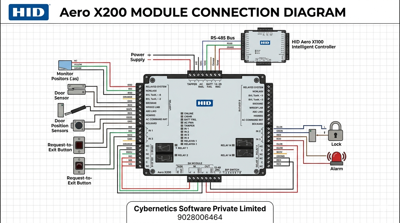
General-Purpose Inputs (IN 1–16)1 twisted pair, 22 AWG, max 500 ft. Supervised: 1kΩ/1kΩ EOL near sensor. Unsupervised: direct NO or NC contact connection
Dedicated Inputs (Tamper, AC Fail, Batt Fail)Wired to cabinet tamper switch, AC power supply fault output, and battery backup status output respectively
Relay 1 & 2 (Form-C)C (Common), NO (Normally Open), NC (Normally Closed) contacts — rated 2A @ 30V DC. Wire output device between C and NO or C and NC as required
Power Input (12–24V DC)Minimum 18 AWG wire, observe polarity. Connect earth ground at ONE location in system only
RS-485 to X1100 / Previous Module1 twisted pair, 24 AWG shielded, 120Ω, max 4,000 ft. Set J1 jumper to "IN" if X200 is last device on bus
RS-485 to Next ModuleContinue daisy-chain to next X200, X100, or X300 module. Do NOT install termination resistor on intermediate modules
Termination Jumper J1 — Critical Installation Note
The HID Aero X200 installation guide (PLT-04235) specifies that if the X200 is the last device on the RS-485 communication bus, the J1 jumper must be set to the "IN" position to apply proper RS-485 bus termination. If the X200 is an intermediate device in the daisy-chain (i.e., another module connects after it), J1 should be in the "OUT" position. Incorrect termination will cause RS-485 signal degradation and unreliable communication between the X200 and the X1100 controller.
HID Aero X200 — Complete Wiring Reference
Cable types, maximum run lengths, and wiring guidance for each interface on the HID Aero X200 Input Monitor Module
Power Supply
// 12–24 V DC INPUT
- Input: 12–24 V DC ±10%
- Minimum wire gauge: 18 AWG
- Must be powered from a UL294 Certified limited power source
- Observe DC polarity — incorrect polarity will damage the module
- Connect earth ground at ONE location in system only — avoid multiple ground connections which cause interference
- Power cable: 2-conductor shielded, 18–16 AWG, max 500 ft (150 m)
General-Purpose Inputs (IN 1–16)
// SUPERVISED OR UNSUPERVISED
- Cable: 1 twisted pair, typically 22 AWG — max 500 ft (150 m); max 30 inputs per run
- Unsupervised: Connect NO or NC contact directly — no resistors needed
- Supervised: Install two 1kΩ, 1%, 1/4 watt EOL resistors close to the sensor device
- Custom EOL thresholds configurable per input via host software
- 4-state detection: open, closed, short, tamper (with ADC on supervised inputs)
- Each input independently configurable as supervised or unsupervised
Dedicated Inputs (Tamper, AC Fail, Batt Fail)
// FIXED FUNCTION — CANNOT BE REPURPOSED
- TAMPER: Wire to cabinet/enclosure tamper switch — triggers alert if enclosure is opened
- AC FAIL: Wire to AC fail contact output of the UPS or supervised power supply — detects mains power loss
- BATT FAIL: Wire to battery low/fail contact output of the UPS — detects backup battery depletion or fault
- All three dedicated inputs are always active and cannot be disabled or reassigned
- Use the same cable spec as general inputs: 22 AWG twisted pair, max 500 ft (150 m)
Relay Outputs (RELAY 1 & 2)
// FORM-C · 2A @ 30V DC
- 2 Form-C relays — each with C (Common), NO (Normally Open), NC (Normally Closed) contacts
- Rated 2A @ 30V DC resistive — non-latching (returns to rest when de-energised)
- For most applications: wire output device between C and NO (or C and NC as required)
- Output cable: 2-conductor, max 500 ft (150 m); minimum gauge depends on current draw
- If controlling inductive loads (solenoids, coils), use a flyback diode across the load
RS-485 Module Port
// TO X1100 AND DAISY-CHAIN
- Cable: 1 twisted pair, shielded, 120Ω impedance, 24 AWG (minimum)
- Maximum total RS-485 bus length: 4,000 ft (1,219 m)
- Multi-drop capable — multiple X200 modules daisy-chain along the same bus
- Connect to X1100 IO Module port, or to previous module in chain
- Continue chain to next X200/X100/X300 from same port terminals
- Set J1 jumper to "IN" only if X200 is the LAST device on the bus
- Do NOT set J1 to "IN" on intermediate X200 modules
HID Aero X200 Status LED Reference
LED indicators on the X200 module for on-site diagnostics and commissioning (PLT-04235, Rev. A.3)
ONLINE LED — Heartbeat & Host Status
Offline (no host comm): 1 second rate, 20% ON. Online with encrypted communication: rapid triple-flash pattern: 0.1s ON · 0.1s OFF · 0.1s ON · 0.1s OFF · 0.1s ON · 0.3s OFF — repeating. Indicates successful AES-256 encrypted communication with X1100.
RS-485 COMM LED
Indicates RS-485 communication activity on the SIO communication port. Flashing confirms the X200 is actively communicating data with the X1100 controller on the RS-485 bus.
RELAY 1 & 2 LEDs
OFF = Relay de-energised (normal rest state — NC closed, NO open). ON = Relay energised — output device activated (NC open, NO closed).
INPUT LEDs (IN 1–16)
Each input LED reflects current state. If the input is defined and active, the LED pulses to its opposite state for 0.1 seconds every 3 seconds. Otherwise the LED is OFF. This allows quick visual identification of active alarm inputs during diagnostics.
Reading the Online LED Pattern
The X200's ONLINE LED encrypted communication pattern (triple-flash) is the key commissioning confirmation — it indicates the X200 has established encrypted RS-485 communication with the X1100 controller. If you see a slow heartbeat (1 second, 20% ON) instead, the module is not yet communicating with the X1100 — check RS-485 cable, termination jumper J1, and address DIP switch settings.
HID Aero X200 — Available Variants
Two variants of the X200 — standard X200 and X200A (Variant B) — both providing the same 16-input monitoring capability
HID Aero X200
Standard Input Monitor Interface Module
- 16 general-purpose supervised/unsupervised inputs
- 3 dedicated inputs: Tamper, AC Fail, Battery Fail
- 19 total inputs per module
- 2 Form-C relay outputs (2A @ 30V DC, non-latching)
- 1 RS-485 port for X1100 connection and daisy-chain
- AES-256 encryption to X1100 controller
- Crypto chip key protection
- Custom rules engine integration via X1100
- Direct replacement for HID VertX V200
- DIN rail compatible mounting
HID Aero X200A (Variant B)
Input Monitor Interface Module — Variant B
- Same hardware specification as X200
- 16 general-purpose inputs + 3 dedicated inputs (19 total)
- 2 Form-C relays, AES-256 encryption, crypto chip
- Different terminal / connector layout (Variant B)
- Used where Variant B physical terminal layout is required
- Functionally identical to X200 in access control software
- Interchangeable with X200 from a software configuration perspective
Frequently Asked Questions — HID Aero X200
Technical and procurement questions about the HID Aero X200 Input Monitor Interface Module
What is the HID Aero X200?
What is the difference between the HID Aero X200 and the HID VertX V200?
How many inputs does the HID Aero X200 have?
What is the custom rules engine in the HID Aero X200?
What are the relay outputs on the HID Aero X200?
How does the RS-485 termination jumper J1 work on the X200?
Need HID Aero X200 Modules for Your Project?
Cybernetics Software is an authorised HID Global NAS partner. We supply HID Aero X200 input monitor modules, design the complete access control and alarm monitoring system, install, and support — across Pune and pan India.
+91-9028006464